Get Up to 60% Off Steps – Shop Now
STEP OUT BRILLIANTLY
RealTruck AMP PowerStep™ Vision
REALTRUCK AMP POWERSTEP™ VISION
The new AMP PowerStep™ Vision represents the latest and greatest in PowerStep™ technology by combining the ease and convenience of a power retracting step with built-in full-length lighting. During regular step operation, AMP PowerStep™ Vision provides effective ground illumination only to transform to customizable accent lighting anytime. Its intuitive design automatically deploys when you open a door or choose to take full command of your power steps and lighting functions via your smartphone and the AMP Research SmartSeries app.
FLUSH LIGHTS
Full-length LED Glow Light seamlessly integrated into the contours of the AMP PowerStep™ Vision powered step for an upgraded illumination experience.
LET THERE BE LIGHT
Light projects at full brightness when the step is activated, then dims output for a cool running accent light feature with color-changing functionality.
APP FOR AMP
Utilizes the convenient AMP Research SmartSeries app for iOS / Android devices to give the user total control of all step and LED lighting functions including manual step override.
PLUG-N-PLAY
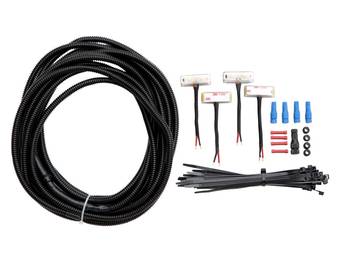
Easy to install with Plug-n-Play technology and all necessary wiring and hardware included.
Select Your Vehicle
Only display items that ship the quickest
FAQs
PowerStep Installation & Troubleshooting Tips
If you need help installing or troubleshooting your AMP PowerSteps, please refer to our Troubleshooting Guide
Maintenance
How to clean your steps
Cleaning your PowerStep
In adverse conditions, debris such as mud, dirt, and salt may become trapped in the running board mechanism, possibly leading to unwanted noise, or binding.
Prepare for cleaning
Manually set the running boards to deploy:
The running boards can me manually set in the deployed position by opening the door, and then place your foot on the step. Leave firm pressure with your foot on the step while you close the door. This will leave your steps in the deployed position.
How to maintain your steps:
Using a pressure washer to clean the front and rear linkages which are all 4 hinge points for your PowerSteps. Avoid spraying the motors directly.
After washing, apply silicone spray (dry Film lubricant) only, to all 4 linkage arms and all pivot pins, some of these pins will be located up high on the linkage arm as well. Then cycle the door to work the lubrication in to the hinge points.
Do not apply silicone, wax, or protectants like Armor All® to the running board. Do not lubricate with any greases, oils, WD-40, or penetrants.
This cleaning should be done periodically, or when debris such as mud, dirt or salt becomes trapped in the running board mechanism.
If you have further questions, please reach out to our technical support team at 1-888-983-2204
Deployment of PowerSteps
Step is clicking when deploying or retracting
Bolt & Wedge Adjustment
Remove motor from side that is being effected.
Allow step to rest in the fully deployed or down position.
Unscrew ¼ -20x7/8 socket head or gold colored hex cap screw located at the top of the linkage arm in the rear.
Loosen 3-4 turns and strike the head of the bolt with a hammer lightly to push wedge loose from the linkage arm. (note: threaded hole on wedge is not in the center of the wedge.)
Apply light pressure to the running board and reinstall wedge and bolt.
Torque bolt to 12ft lbs.
Re install motor and retest.
If you have any questions or concerns reach out to our technical support team at 1-888-983-2204
My LED lights will not shut off or are not turning on.
Testing LED light voltage
Start by closing all doors on the vehicle
Locate the small 8 pin plug located at your controller. (pic attached labeled override pinning can be used)
Using a DMM (digital multimeter) insert the red lead of your meter into the back of the controller at the red wire.
Insert your black lead into the back of the controller at the black wire.
Set to Volts DC on your meter.
When you open any door your meter should display 12v + or battery voltage and when the door is closed the voltage should go away.
If you are not seeing the voltage effected by the operation of the door proceed to the next step.
Unplug small 8 pin plug from the controller.
Using your multimeter, meter out the pins directly in the controller and run the same test as previous.
If you are seeing that voltage is staying constant no matter if you open or close any door you may be experiencing an issue with the controller.
If you are receiving voltage when you open the door and it goes away when you close the door you may be experiencing an issue in the harness or with your LED lights.
If you have further questions, please reach out to our technical support team at 1-888-983-2204
How do I replace a clutch gear or drive shaft?
Click here for the Clutch Gear Change
If you have any questions or concerns reach out to our technical support team at 1-888-983-2204
Disconnected the vehicles battery and my steps no longer deploy or retract.
If you are experiencing this issue, you may have a component in the system that received a spike in voltage. If you believe you may be experiencing this issue, follow the steps below:
Controller Reset:
Locate Amp Research Controller under the hood. The controller will have a red wire going from the red + terminal of the battery directly to the controller.
Locate fuse holder on red wire going to the controller.
Remove the 30/40-amp fuse to the system.
Verify both locking clips are fully locked into the controller.
Push each one of the wires individually deep into the controller.
Let the system sit for 5 minutes.
Reinstall the fuse into the controller and retest.
If your issue is not resolved proceed to the next step.
Controller vs. OBDII Failure:
Complete controller reset procedure before performing this test.
Locate OBDII module plug under dash. This will be plugged in to the vehicles diagnostic port and look like the image below:
Follow black pigtail off side of plug till it splits in to 2 purple wires. (Note: One is purple, and one is purple/black stripe)
Disconnect purple and purple/black stripe wires from splice point under dash.
Put OBDII plug to the side it will not be used.
Locate a solid chassis ground location in the vehicle. (Note: Chassis ground locations can be found on any non-painted bare metal location in the vehicle. If one cannot be found, then a jumper wire from the “- “or black terminal of the battery can also be used)
Ground both purple wires to chassis ground location. This can be performed with both wires at the same time or each wire individually. These are our trigger wires, one driver and one passenger.
When chassis ground is applied to wires it will deploy the step and when ground is removed it will retract the step.
If you are experiencing no deployment and lights for steps are not illuminating you may have a controller failure.
If steps start to deploy and retract when ground is applied and removed, then you may have an OBDII failure.
If you have further questions, please reach out to our technical support team at 1-888-983-2204
I believe my motor has failed.
If you believe you are experiencing an issue with a motor that has failed, follow the steps below:
Testing Power to Motor:
(Note: You will need a digital multimeter to perform this test)
Locate the plug at the motor.
Remove plug from the motor.
Using a digital multimeter set meter to volts DC (symbol below)
Insert the red lead of the multimeter into the orange wire black lead into the white wire of the motor plug. (Note: One side of the vehicle will have a solid orange and solid white wire and the other will have orange/black stripe and white/black stripe. If you are not able to remove the plug pierce the wire with DMM lead to complete test)
With multimeter visible open the door on the side of the vehicle the motor we are testing is located.
The meter should display battery voltage for 5 seconds and return to zero. (Note: To check for battery voltage touch red and black lead of meter directly to red and black posts of battery under the same volts DC setting on meter)
Close door and meter should display -battery voltage for 5 seconds and return to zero. (Note: It doesn’t matter if you display “- “or “+” voltage during door open or door close operation just that we are getting voltage for 5 seconds before returning to zero)
If you receive voltage for less than 5 seconds or only in one direction, we may have an issue with the controller.
If test shows accurate voltage readings, then we may be experiencing binding in the linkage or an issue with the motor.
If you want to confirm you are having an issue with your motor, simply switch the motors from side to side and see if the issue follows the motor. (Note: This step will only work if one side has failed, and the other side is working)
If both sides have failed, you can unplug the motor and manually put 12v power+ and ground- to each of the pins on the motor to check if it will move. One contact gets positive+ and the other gets a ground- and the motor moves one way, then you switch the configuration, and the motor will spin the other.
If you have any questions or concerns reach out to our technical support team at 1-888-983-2204
One or both PowerSteps will not deploy/retract.
If you are experiencing this issue, it may be originating from a few possible areas. Follow the steps below to help isolate where the failure may be coming from:
Controller Reset:
Locate Amp Research Controller under the hood. The controller will have a red wire going from the red + terminal of the battery directly to the controller.
Locate fuse holder on red wire going to the controller.
Remove the 30/40-amp fuse to the system.
Verify both locking clips are fully locked into the controller.
Push each one of the wires individually deep into the controller.
Let the system sit for 5 minutes.
Reinstall the fuse into the controller and retest.
If your issue is not resolved, please proceed to the next step.
Testing Power to Motor:
(Note: You will need a digital multimeter to perform this test)
Locate the plug at the motor.
Remove plug from the motor.
Using a digital multimeter set meter to volts DC (symbol below)
Insert the red lead of the multimeter into the orange wire black lead into the white wire of the motor plug. (Note: One side of the vehicle will have a solid orange and solid white wire and the other will have orange/black stripe and white/black stripe. If you are not able to remove the plug pierce the wire with DMM lead to complete test)
With multimeter visible open the door on the side of the vehicle the motor we are testing is located.
The meter should display battery voltage for 5 seconds and return to zero. (Note: To check for battery voltage touch red and black lead of meter directly to red and black posts of battery under the same volts DC setting on meter)
Close door and meter should display -battery voltage for 5 seconds and return to zero. (Note: It doesn’t matter if you display “- “or “+” voltage during door open or door close operation just that we are getting voltage for 5 seconds before returning to zero)
If you receive voltage for less than 5 seconds or only in one direction, we may have an issue with the controller.
If test shows accurate voltage readings, then we may be experiencing binding in the linkage or an issue with the motor.
If you have any questions or concerns reach out to our technical support team at 1-888-983-2204
PowerSteps are no longer deploying or retracting.
If your steps are no longer deploying or retracting and the LED lights for the steps no longer light up, you may be experiencing an issue with your controller or OBDII module plug if the kit is a plug and play.
Follow the steps below to help identify where the issue may be coming from:
Controller vs. OBDII Failure:
Complete controller reset procedure before performing this test.
Locate OBDII module plug under dash. This will be plugged in to the vehicles diagnostic port and look like the image below:
Follow black pigtail off side of plug till it splits in to 2 purple wires. (Note: One is purple, and one is purple/black stripe)
Disconnect purple and purple/black stripe wires from splice point under dash
Put OBDII plug to the side it will not be used
Locate a solid chassis ground location in the vehicle. (Note: Chassis ground locations can be found on any non-painted bare metal location in the vehicle. If one cannot be found, then a jumper wire from the “- “or black terminal of the battery can also be used)
Ground both purple wires to chassis ground location. This can be performed with both wires at the same time or each wire individually. These are our trigger wires, one driver and one passenger.
When chassis ground is applied to wires it will deploy the step and when ground is removed it will retract the step.
If you are experiencing no deployment and lights for steps are not illuminating you may have a controller failure.
If steps start to deploy and retract when ground is applied and removed, then you may have in OBDII failure.
If you have any questions or concerns reach out to our technical support team at 1-888-983-2204
Testing for binding in linkages
If you believe you are experiencing an issue with binding or seized linkages follow the steps below to test:
Clean PowerSteps following the cleaning procedure shown below:
Remove motor to the PowerStep.
The step will rest in the down position after the motor has been removed so use caution.
From the center of the board, move the step to the fully retracted position remaining cautious of any resistance in the linkage arms.
From the retracted position, keeping legs at a safe distance release board.
The board should return to the fully deployed position quickly.
If any resistance is felt in the linkages when putting the boards in the fully retracted position or if the board falls to the fully deployed position slowly then proceed to the next step.
Remove board from linkage arms.
Individually put each linkage up and down and feel for resistance or binding.
If you feel resistance or experience binding, then that linkage may need to be replaced.
If you are unsure if you are experiencing resistance or binding and you are only experiencing this on one side, then remove the board on the working side and run the same test on the other side.
Using a stopwatch, time both sides to verify that the linkages are dropping at a similar rate of speed consistently.
If you have any questions or concerns reach out to our technical support team at 1-888-983-2204
PowerStep Installation & Troubleshooting Tips
If you need help installing or troubleshooting your AMP PowerSteps, please refer to our Troubleshooting Guide
Vehicle Specific Questions
Kit # 76236-01A, 76242-01A, 77236-01A, 77242-01A, 78236-01A, 78242-01A, 86236-01A, 86242-01A
Identifying Sync3 or Sync4 Radios
Go to home screen on radio.
Click on "Settings" in lower right hand corner.
Click on "General" that is displayed in the settings menu.
Scroll down to "About Sync."
Sync Version will be displayed at the top of the "About Sync" information page.
If you have any questions or concerns reach out to our technical support team at 1-888-983-2204
New 22-23 GM 1500 Refresh / 21-23 GM SUV OBDII Wiring Locations (excludes new Escalade)
When having to wire in the blue and white wire to the vehicles BCM in the driver side kick panel, you will need to make sure we are wired into the locations shown in the photos below.
If you plan to unplug the BCM plug from the BCM to make your connections make sure you have first disconnected the battery.
After making connections, if you are experiencing only the back doors are deploying the step check your connection for the white wire in the green plug. There are 2 of the same color wire in this plug and you may be experiencing a connection issue, or you may be tapping into the incorrect wire location.
After making connections, if you are experiencing only the Front doors are deploying the step check your connection for the blue wire in the grey plug. You may be experiencing a connection issue, or you may be tapping into the incorrect wire location.
If you have any questions or concerns reach out to our technical support team at 1-888-983-2204
Kit # 75113-01A Silverado 1500 Extended Cab mounting Issues
Click here for 75113-01a GM 1500 Extended Cab Mounting Instructions
If you have any questions or concerns reach out to our technical support team at 1-888-983-2204
Steps retract, but do not deploy; Kit# 76239-01A/77239-01A/78239-01A/76243-01A; Fits 18-22 Ram 1500-3500, 1500 Classic; All Cabs
If you are experiencing this issue, it most likely has to do with an incorrectly placed can bus connection.
Locate the blue and white wire at the OBDII plug supplied by Amp Research.
Verify that the connector at the end of the blue and white wires is plugged into the Green, double row can bus port located up high in the dash.
The recommended port is in the lower left-hand corner of the dual row receptacle.
If the lower left-hand port is already occupied, connect to the first available open port from the bottom in the dual row Green receptacle. Photo below:
If you have any questions or concerns reach out to our technical support team at 1-888-983-2204
Front idler linkage is sagging when retracted; Kit# 76140-01A; Fits 19-22 Ranger/Bronco
If you are experiencing this issue, it is most likely needs to be adjusted.
Start by following the torque procedure below:
If you are still experiencing issues move to the next step and perform the adjustment below.
If everything is tight deploy the step, loosen the rear mounting points at the body. Remove the bolts and break the board free from the front linkage. Lift the board off the lower mount about 2”. While holding the board up tighten the body mounts. Reinstall board to front lower mount and retest.
If you have any questions or concerns reach out to our technical support team at 1-888-983-2204
Unable to mount front motor linkage to front mounting location, pointing towards front wheel; Kit# 75122-01A/77122-01A/78122-01A/75132-01A/77132-01A/78132-01A/75135-01A/77135-01A/78135-01A: Fits Wrangler JKU/JL, Gladiator
If you are experiencing this issue, it is most likely due to not mounting to the correct mounting location.
Front linkage should be mounted to the mounting location to the rear of the front door similar to the illustration shown below.
Please refer to instructions for more detail.
If you have any questions or concerns reach out to our technical support team at 1-888-983-2204 Mon-Fri 7:00am – 5:00pm PST
Steps retract, but one or both steps are sagging in the front; Kit# 76254-01A Fits 19-21 Slv/Sra 1500,22 LTD/Lmtd, 20-22 Slv/Sra HD, Db/Cw
If you are experiencing this, then the rear motor linkage mounting location needs to be adjusted.
Crew cabs should be mounted to the mounting location 16” from the back of the cab.
If you have confirmed that you are mounted to 16” to the back of the cab and you are having the same issue, then move the linkage to the 33” from the back of the cab mounting location and retest.
If you have any questions or concerns reach out to our technical support team at 1-888-983-2204
Kit has been installed but my steps are working in reverse; Kit# 76254-01A, 77254-01A - Fits 19-21 Slv/Sra 1500, 20-22 Slv/Sra 2500/3500, Crw Cb
If you are experiencing this issue it is most likely caused by having the rear motor linkages on the wrong side of the vehicle. Look at your instructions to verify.
The driver and passenger side rear motor linkages should have the motor mounted on the side of the linkage facing the front tire. If the motor is on the side of the linkage closest to the rear tire, then the entire rear motor linkage arms will need to swap sides. Driver to passenger and passenger to driver.
If you have any questions or concerns reach out to our technical support team at 1-888-983-2204
Warranty Support, Contact Us
I have completed the install and now have some warranty questions.
Please go to Warranty Support and provide all the detailed information and Send Message.
I am installing and I have some install questions, I need to get in contact with tech support
Please go to Contact Us/Tech Support and Choose Technical Support as a Reason, provide all the detailed information and Send Message.
About AMP Research
AMP Research, a RealTruck brand, invented the patented powered running board for trucks, Jeep® brand vehicles, SUVs, and vans. Our groundbreaking products exemplify “Innovation in Motion” from the original PowerStep and versatile BedXTender HD to the PowerStep Smart Series, a Bluetooth-enabled electric running board controlled via a convenient smartphone app.
We offer a limited 3 year/36,000 mile warranty on BedStep & BedXTender models, and a 5 year/60,000 mile warranty on PowerStep
Warranty Registration
Looking for expert installation and superior service? Use our locator to find a dealer near you.
Find A Dealer
Search for your AMP Research product by name or part number to find our detailed user manuals and installation guides.
